How to Draw Pictures, Part 1: Contours
Computer graphics research has come to understand drawing very well. Based on very simple principles, our algorithms can render objects in many different artistic styles. These renderings are often good enough to fool a viewer into thinking they were drawn, painted, or sketched by hand. We can do this all without any machine learning or training data. These techniques have been used to make new kinds of animations and games.
I think this is pretty amazing, but it does not seem to be very widely known.
This article gives a non-technical introduction to line drawing algorithms. In two follow-up articles, I will discuss improvements and extensions that make these algorithms increasingly powerful at capturing many different artistic styles. This research area is called “Non-Photorealistic Rendering.” In later articles, I will discuss how these methods inform theories of perception and art.
Together, these algorithms represent a generative theory of representational art. Studies of visual art from other disciplines typically describe loose trends or properties of art, describing qualitative visual traits like color balance or symmetry. In contrast, algorithms can give explicit recipes for how to create line drawings. Hence, they provide a new, complementary form of understanding, unavailable to previous ways of studying and teaching art. Like any theory, these theories are incomplete models of the world; they won’t explain all the specifics of each artist’s individual choices.
For complete details and references on the material here, see this technical tutorial.
Cameras
Before we get started, I will quickly summarize the linear perspective model used in computer graphics. Linear perspective was invented in the Renaissance—it was the first mathematical model used in realistic art. It is also called the pinhole camera model, and it is now one of the foundations of computer graphics.
In linear perspective, we imagine that the viewer’s eye—or the camera center—is a single point in space, and there is an invisible plane between the scene and the viewpoint, called the image plane. Imagine drawing a line between a point in the scene and the viewer’s eye. The point where this line intersects the image plane is where you draw that point.
Here’s one depiction of linear perspective, from the 16th-century:
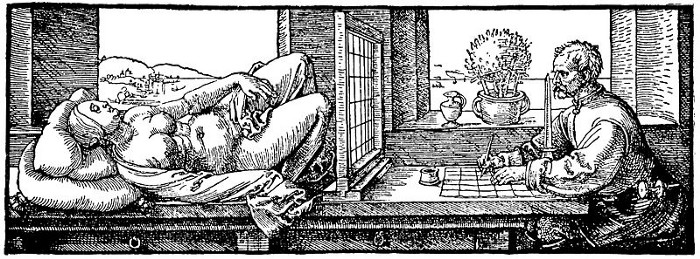
The artist shown here is drawing a picture on the grid on the table. To draw where part of the model goes in the grid, say, her eye, he sees where her eye appears in the grid, and draws her eye in the corresponding box on the grid on the table. This summarizes the basic rendering procedure used in most computer graphics.
Contours
We can now explain contours. As a starting point, suppose we have a single 3D object that we want to draw, like this pig:

As in any image on a computer, the image consists of a grid of small pixels. Let’s plot, for each pixel, the distance of that pixel from the viewer:

What happens if we find the edges in this image? That is, we mark all pixels that are next to a very different depth as black, and the rest as white:
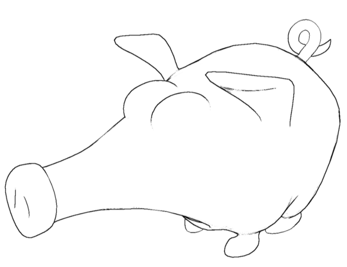
With this simple procedure we have something that starts to look like a line drawing. These curves are called the occluding contours, and drawing occluding contours is the foundation of realistic line drawing.
Let’s look at the shape from a different point of view:
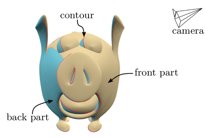
This is the same pig, but seen from the front, and rendered in a different color scheme. The object can be split into three regions: the front part (in yellow), which faces the camera; the back part (in blue), which faces away from the camera, and the contour (in red), which separates the two. The front part is usually visible, and the back part is never visible. This means that the contour separates visible parts of the surface from hidden parts.
It can take awhile to wrap one’s head around the geometry of contours. Don’t worry if it’s difficult to see at first.
Basic Stylization
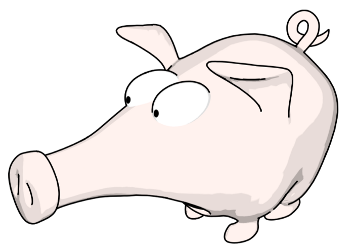
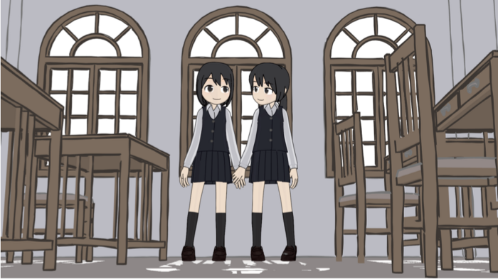
Once we have the contours, we can create different kinds of stylized rendering. For example, we can put them on top of a “toon shaded” rendering to create a cartoon style:
Or we can draw just the contours, but use stylized curves that look like brush strokes:

Perhaps it looks a bit like Japanese sumi-e ink brush painting, but there’s a ways to go to make it look really convincing.
Here are some more sophisticated examples of different contour rendering styles, made by different artists using Blender’s Freestyle plugin:
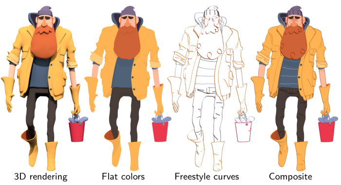
In each case, the contour lines are drawn with different colors, and the objects are rendered either with flat shading or as transparent.
Conclusion
Contours are a very simple kind of curve, but they can be used to create many lovely and convincing types of drawings. If you would like to learn more about the mathematics and algorithms of these curves, please see our tutorial.
In the next article in this series, I describe an extension to these curves that makes them even better. I also describe scientific studies to answer the question: how well do these curves describe how humans draw pictures?
Image credits
The pig model was created by Keenan Crane. Except where noted, all renderings here were created by Pierre Bénard for our tutorial.